| SPLIT SHEATH INSERTION |
|
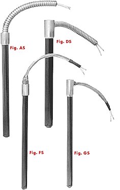
Fig. AS Stainless Steel Armor Cable Lead Protection Armor cable is the best protection against abraision or other damage to lead wires. A straight transition adaptor with 12&quit; stainless steel armor cable and 14" lead wires is standard. Specify longer length. Fig. DS Right Angle Stainless Steel Armor Cable Lead Protection Figure DS shows an SST insertion heater with right angle stainless steel armor cable protected leads. Figure DS is for use where spacing is limited and for wiring convenience. 12 " cable and 14" overall length leads are standard. Specify longer length. Fig. FS Flexible Stainless Steel Braided Leads Figure FS flexible stainless steel braid protects leads from sharp edges. The braided sleeving is virtually as flexible as non-protected leads. 12" stainless steel braid with 14" leads are standard. Specify longer length. Fig. GS Right Angle Flexible Stainless Steel Armor Cable Lead Protection Figure GS right angle flexible stainless steel braid protects lead wires from abrasion and are full length flexible at a right angle orientation for installations with limited spacing. 12" stainless steel braid with 14" leads are standard. Specify longer lengths. |
|||||||||||||||||||||||||||||||||||||||||||||||||||||||||||||||||||||||||||||||||||||||||||||||||||||||||||||||||||||||||||||||||||||||||
** Not applicable to Fig. FS or GS.
|
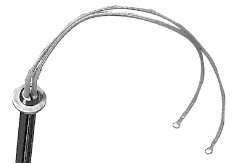
Fig. WS Mounting Flange Figure WS is a stop washer or mounting flange. Specify distance from lead end, outside diameter and mounting hole centers, if required.
Ordering Information Specify:
|
|||||||||||||||||||||||||||||||||||||||||||||||||||||||||||||||||||||||||||||||||||||||||||||||||||||||||||||||||||||||||||||||||||||||||